2020 Knowledge points of wireless network coverage system

What is AP?

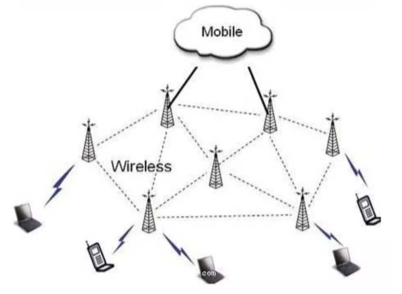
AP-Wireless Access Point (WirelessAccessPoint) AP is the HUB in the traditional wired network, and it is also the most commonly used equipment when building a small wireless LAN.

AP is equivalent to a bridge connecting wired and wireless networks. Its main function is to connect various wireless network clients together, and then connect the wireless network to the Ethernet to achieve the purpose of network wireless coverage.

AP is divided into thin and fat?

Thin AP (FITAP):

Also known as wireless bridges, wireless gateways, and so-called “thin” APs.

Popular understanding of thin AP: It cannot be configured by itself, and a dedicated device (wireless controller) is required for centralized control and management configuration.

“Controller + thin AP + router architecture” is generally used for wireless network coverage, because when there are a large number of APs, only the controller is used to manage the configuration, which will simplify a lot of work.

Fat AP (FATAP):

The so-called fat AP in the industry is also called a wireless router. A wireless router is different from a pure AP. In addition to the wireless access function, it generally has two interfaces, WAN and LAN, supports address translation (NAT), and supports DHCP server, DNS and MAC address cloning, as well as VPN access, firewall and other security Features.

What is AC?

The Wireless AccessPoint Controller is a network device used to centrally control the controllable wireless APs in the local area network. It is the core of a wireless network and is responsible for managing all wireless APs in the wireless network. The management of APs includes: Send configuration, modify related configuration parameters, radio frequency intelligent management, access security control, etc. (All ACs and APs currently circulating in the market are from the same manufacturer to manage each other)

What is a POE switch?

POE (PowerOver Ethernet) POE is also known as a local area network-based power supply system (PoL, Powerover LAN) or Active Ethernet (Active Ethernet), sometimes also referred to as Power Over Ethernet, which refers to the existing Ethernet Cat .5 Without any changes to the wiring infrastructure, while transmitting data signals for some IP-based terminals (such as IP telephones, wireless LAN access points, network cameras, etc.), it can also provide DC for such devices Power supply technology.

POE technology can ensure the normal operation of the existing network while ensuring the safety of the existing structured cabling, minimizing costs.

The POE switch can not only provide the transmission function of the ordinary switch, but also provide the power supply function to the other end of the network cable. The integration of power supply + data transmission does not require an additional power supply module or POE power supply module to supply power to the device, and a Cat.5 cable completes all the work.

PoE power supply difference

Standard poe: According to the IEEE802.3af/at specification, it is necessary to first detect the 25K characteristic resistance of the receiving terminal and perform a handshake. Only when the handshake is successful, can the power supply be supplied; otherwise, only data (data) is passed.

Example: Plug the POE power supply into the computer network card, the computer network card will not be burned, only normal Internet access because the data can pass.

Non-standard POE: also called forced supply type, the AC power is supplied as soon as the power is turned on; the receiving terminal is not detected first, and the handshake is not performed, and the power is directly 48V or 54V. 

Example: Plug the POE power supply into the computer network card, you can go online normally, but if you don’t negotiate to directly supply 48 or 54V, it may burn the device.

There are roughly 48V, 24V and 12V output voltages (DC) on the market

The software and hardware needed to deploy wireless engineering?

Basic hardware: router POE switch AC controller wireless AP

High-end hardware: firewall router traffic and behavior management bypass main switch floor switch POE switch AC controller wireless AP

Is the greater the power of the AP, the better?

No, the higher the power of the AP, the higher the transmitted signal strength. Literally speaking, it will lead you to a misunderstanding. The stronger the signal, the better, but the stronger the signal is for itself, which is transmitted in the entire wireless network. Signals belong to both parties. Both the transmitter and the receiver will transmit data to each other. If the signal at the transmitter is too strong, it will inevitably affect the return of data from the receiver, which will cause network transmission delays or packet loss.

Popular understanding: In a space, you and another person are talking at the same time, and the other person’s voice is too loud, and your voice is too small, which will cause the other person to not hear what you are saying, thus affecting the quality of the call.

In a large-scale wireless project, what are the key points and the most important points?

Key points of engineering perspective:

design

The actual construction drawing, determining the routing position of the wiring, need to consider such as: concealment, damage to the building (characteristics of the building structure), avoiding power lines and other lines while using the existing space, and pairing cables in the field Necessary and effective protection needs.

The location of the router

The router is generally selected in an underground weak current room (far away from a strong current room to avoid strong electromagnetic interference). Pay attention to ventilation and keep it dry. It is best to have a cabinet and put it together with the core switch.

POE power supply switch location

The location of the POE switch should be selected reasonably, located in the middle of the AP point, to reduce wiring costs and shorten the distance between the switch and the AP.

AP location selection

The point layout of the AP selects the central area of the scene and radiates it toward the periphery. The coverage areas of AP parts should overlap to reduce signal blind areas. The distance between the AP and the POE switch should not exceed 80 meters (a genuine Anpu network cable as an example)

Network cable laying

As the transmission carrier of the network signal, the network cable should be protected during the laying process, and there should be no breaks or dead angles. If necessary, iron pipes should be worn or placed in the roof bridge. Special attention is paid to the principle of high-voltage wires to reduce interference to the signal.

Precautions for practical debugging and post-maintenance:

a. External network and routing: The external network cable is connected in place to ensure the normal Internet access conditions of the line, and the routing is connected to ensure that the routing itself can normally communicate with the Internet. During the construction, the main exchange and the construction floor exchange are connected to ensure the normal communication of the backbone network.

b. Debug walkie-talkie: During the commissioning stage, a set of walkie-talkie equipment needs to be seconded to the mall to facilitate the debugging work.

c. During the construction and debugging stage, sufficient spare parts shall be reserved for AP, switch, network cable, and other construction and debugging hardware.

d. Construction drawings: Before each construction, please ask the constructor to give us two copies of the construction drawings.

Construction network topology: requirements, detailed floor switches, routing information and location, number of APs on each floor, and connection methods.

Construction equipment connection line identification diagram: requirements, routing and switch and AP connection information, corresponding ports, etc., all connection lines are theoretically approximate network cable length (including road-switch-AP).

e. Construction wiring and line marking planning:

Information identification record: AP point Mac information record: when the construction party places the AP location, it is necessary to record the floor number and location number of the AP and the corresponding Mac information (note the corresponding floor plan AP number, for example: 1st floor No. 1 mac information format is 1F- 1: AC:11:22:33:44:AP ). This information is uniformly recorded in the Word document floor shopping mall construction drawing according to the floor distribution or directly manually recorded in the free space on the side of the construction drawing, which is convenient for later maintenance and use. 

Wire mark identification record:

(1) The input and output lines of the switch: It is necessary to indicate which floor and location number of the AP connected to the terminal of the identification or serial number, (note the corresponding floor plan AP number, for example: the format of 1st floor 1 is 1F-1), Lines coming in from the external network should also be marked with a cable: “External network access should be marked.”

(2) Interconnection between switches on all floors: The source of the wiring connector with the identification or serial number should be marked at the head of the line interconnection line of the switch. (Pay attention to write the floor and switch label, such as: switch 1 on the first floor, the format is 1F-1 SW)

Check on the spot whether the installed AP is powered on and working normally:

After the construction is completed, the construction personnel shall check all APs on the spot to be energized normally, and the normal state under the power-on condition: the green indicator on the AP is always on. If the routing is in place and running, the software can be used to detect whether the AP normally emits signals and connects to the Internet.

If the above information is completely clear, there is no need for the construction personnel to be on site. If the above information is completely unclear, the construction personnel need to cooperate on site for each commissioning.

The above is the news sharing from the PASSHOT. I hope it can be inspired you. If you think today’ s content is not too bad, you are welcome to share it with other friends. There are more latest Linux dumps, CCNA 200-301 dumpsCCNP Written dumps and CCIE Written dumps waiting for you.

The difference between OSPFv3 and OSPFv2

OSPF is a link state routing protocol. It has many advantages such as open standards, rapid convergence, no loops, and easy hierarchical design. The OSPFv2 protocol, which is widely used in IPv4 networks, is too closely related to IPv4 addresses in terms of message content and operating mechanism, which greatly restricts its scalability and adaptability.

Therefore, when we first considered extending OSPF to support IPv6, we realized that this was an opportunity to improve and optimize the OSPF protocol itself. As a result, not only did OSPFv2 be extended for IPv6, but a new and improved version of OSPF was created-OSPF v3.

OSPFv3 is described in detail in RFC2740. The relationship between OSPFv3 and OSPFv2 is very similar to the relationship between RIPng and RIPv2. The most important thing is that OSPFv3 uses the same basic implementation mechanism as OSPFv2-SPF algorithm, flooding, DR election, area, etc. Some constants and variables like timers and metrics are also the same. Another similarity to the relationship between RIPng and RIPv2 is that OSPFv3 is not backward compatible with OSPFv2.

Whether it is OSPFv2 or OSPFv3, the basic operating principles of the OSPF protocol are the same. However, due to the different meanings of the IPv4 and IPv6 protocols and the size of the address space, the differences between them are bound to exist.

Similarities between OSPFv2 and OSPFv3: 

1. The router types are the same. Including internal routers, backbone routers, area border routers and autonomous system border routers.

2. The supported area types are the same. Including backbone area, standard area, stub area, NSSA and completely stub area.

3. Both OSPFv2 and OSPFv3 use SPF algorithm.

4. The election process of DR and BDR is the same.

5. The interface types are the same. Including point-to-point links, point-to-multipoint links, BMA links, NBMA links and virtual links.

6. The data packet types are the same, including Hello, DBD, LSR, LSU, and LSA, and the neighbor relationship establishment process is also the same.

7. The calculation method of the metric value has not changed.

The difference between OSPFv2 and OSPFv3:

1. In OSPFv3, the “subnet” concept of OSPFv2 is changed to the “link” concept, and two neighbors on the same link but belonging to different IPv6 subnets are allowed to exchange data packets.

2. The router ID, area ID, and LSA link state ID values are still expressed in 32 bits, so they cannot be expressed in IPv6 addresses.

3. On the link between the broadcast network and the NBMA network, OSPFv2 neighbors are identified by their interface addresses, while neighbors on other types of links are identified by RID. OSPFv3 cancels this inconsistency, and all neighbors on all types of links are identified by RID.

4. OSPFv3 retains the area (or AS) and area (area) flooding range of OSPFv2, but adds a link local flooding range. A new link LSA (Link LSA) is added to carry information that is only associated with neighbors on a single link.

5. The IPv6 protocol uses an authentication extension header, which is a standard authentication process. For this reason, OSPFv3 does not require its own authentication for OSPFv3 packets, it only needs to use IPv6 authentication.

6. Use the link-local address to discover neighbors and complete automatic configuration. IPv6 routers do not forward data packets whose source address is the link address. OSPFv3 believes that each router has assigned its own link address for each physical network segment (physical link) it connects to.

7. In OSPFv2, unknown LSA types are always discarded, while OSPFv3 can treat them as link local flooding range.

8. If an IPv4 address is set on the interface of the router, or a loopback interface is set, OSPFv3 will automatically select the IPv4 address as the router ID, otherwise, you need to set the ID number for the router.

The above is the news sharing from the PASSHOT. I hope it can be inspired you. If you think today’ s content is not too bad, you are welcome to share it with other friends. There are more latest Linux dumps, CCNA 200-301 dumpsCCNP Written dumps and CCIE Written dumps waiting for you.

4 filtering ways of spam help your network safety

E-mail is a communication method that provides information exchange by electronic means and is the most used service on the Internet. Through the network’s e-mail system, users can communicate with network users in any corner of the world at a very low price and very fast.

E-mail can be in various forms such as text, image, and sound. At the same time, users can get a lot of free news and special emails, and easily realize easy information search. The existence of e-mail greatly facilitates the communication and exchanges between people and promotes the development of society.

There are many email formats, such as SMTP, POP3, MUA, MTA, etc.

Spam refers to emails sent forcibly without the user’s permission. The emails contain advertisements, viruses, and other content. For users, in addition to affecting normal mail reading, spam may also contain harmful information such as viruses; for service providers, spam can cause mail server congestion, reduce network efficiency, and even become a hacker attacking mail server. tool.

Generally speaking, a dedicated server is used to send spam. Generally speaking, it has the following characteristics:

1. Emails sent without the consent of the user are not relevant to the user.

2. Criminals obtain email addresses through deception.

3. The email contains false advertisements, which will spread a lot of spam.

The anti-spam method is basically divided into technical filtering and non-technical filtering in terms of technology, mainly technical filtering, active filtering, and establishing a filtering mechanism in the process of mail transmission;

Non-technical filtering includes: legal and regulatory documents, unified technical specifications, or social moral advocacy, etc. In the process, mail filtering is divided into server-side filtering and receiving-side filtering. The receiving-side filtering is to check the received mail through the server system program after the mail is sent to the mail server. It is passive filtering, mainly by IP address and keywords. As well as filtering for other obvious characteristics of spam, it is feasible and has a low error rate of normal mail. It is currently one of the main anti-spam methods.

From the beginning of spam, the majority of network providers and Internet companies have begun to make trouble for this. However, it is clear that 30 years of development have not produced effective anti-spam technologies or methods. One of the important reasons is that the situation is huge. The amount of spam and high-complexity filtering technology has not been until recent years, the development of artificial intelligence, machine learning and other disciplines has made progress in anti-spam work.

Common spam filtering methods:

1. Statistical method:

Bayesian algorithm: Based on statistical methods, using the method of marking weights, using known spam and non-spam as samples for content analysis and statistics to calculate the probability that the next email is spam, and generate filtering rules.

Connection/bandwidth statistics: anti-spam is achieved by counting whether the number of attempts to connect to a fixed IP address within a unit time is within a predetermined range, or limiting its effective bandwidth.

Mail quantity limit: Limit the number of mails that a single IP can send in a unit time.

2. List method:

BlackList and WhiteList respectively record the IP addresses or email addresses of known spammers and trusted email senders. This is also one of the more common forms of email filtering. At the beginning of anti-spam activities, this This kind of designated mail filtering is very limited because of the lack of list resources.

3. Source method:

DomainKeys: Use to verify whether the sender of the email is consistent with the claimed domain name and verify the integrity of the email. This technology is a public key + private key signature technology.

SPF (SenderPolicy Framework): The purpose of SPF is to prevent forgery of email addresses. SPF is based on reverse lookup technology to determine whether the specified domain name and IP address of the email correspond exactly.

4. Analysis method:

Content filtering: Filter spam by analyzing the content of emails and then using keyword filtering.

Multiple picture recognition technology: Recognize spam that hides malicious information through pictures.

Intent analysis technology: Email motivation analysis technology.

The sending and receiving of mail generally needs to go through the SMTPServer, and the SMTP server transfers messages through the SMTP (Simple Mail Transfer Protocol) protocol.

The email transmission process mainly includes the following three steps:

① The sender PC sends the mail to the designated SMTPServer.

②The sender SMTP Server encapsulates the mail information in an SMTP message and sends it to the receiver SMTP Server according to the destination address of the mail.

③The recipient receives the mail.

POP3 (Post OfficeProtocol 3) and IMAP (Internet Mail Access Protocol) stipulate how the computer manages and downloads e-mails on the mail server through the client software.

Spam prevention is an IP-based mail filtering technology that prevents the flood of spam by checking the legitimacy of the source IP of the sender’s SMTP Server. The proliferation of spam brings many problems:

① Occupy network bandwidth, cause mail server congestion, and reduce the operating efficiency of the entire network.

②Occupy the recipient’s mailbox space, affecting the reading and viewing of normal mail.

When the firewall is used as a security gateway, all external mails need to be forwarded through the firewall. By checking the IP address of the sender’s SMTP Server, spam can be effectively filtered.

The above is the news sharing from the PASSHOT. I hope it can be inspired you. If you think today’ s content is not too bad, you are welcome to share it with other friends. There are more latest Linux dumps, CCNA 200-301 dumpsCCNP Written dumps and CCIE Written dumps waiting for you.

Detailed interpretation of IPSec protocol

IPSec (Internet Protocol Security) is a set of open network security protocols formulated by IETF (Internet Engineering Task Force). It is not a single protocol, but a collection of protocols and services that provide security for IP networks. It provides high-quality, interoperable, and cryptographic-based security guarantees for data transmitted on the Internet.

IPSec mainly includes security protocols AH (AuthenticationHeader) and ESP (Encapsulating Security Payload), key management exchange protocol IKE (Internet KeyExchange), and some algorithms for network authentication and encryption.

IPSec mainly uses encryption and verification methods. The authentication mechanism enables the data receiver of IP communication to confirm the true identity of the data sender and whether the data has been tampered with during transmission. The encryption mechanism guarantees the confidentiality of the data by encrypting the data to prevent the data from being eavesdropped during transmission. To provide security services for IP data packets.

The AH protocol provides data source authentication, data integrity verification and anti-message replay functions. It can protect communications from tampering, but it cannot prevent eavesdropping. It is suitable for transmitting non-confidential data. The working principle of AH is to add an identity authentication message header to each data packet, which is inserted behind the standard IP header to provide integrity protection for the data.

The ESP protocol provides encryption, data source authentication, data integrity verification and anti-message replay functions. The working principle of ESP is to add an ESP header to the standard IP header of each data packet, and to append an ESP tail to the data packet. Common encryption algorithms are DES, 3DES, AES, etc.

In actual network communication, you can use these two protocols at the same time or choose to use one of them according to actual security requirements. Both AH and ESP can provide authentication services, but the authentication services provided by AH are stronger than those provided by ESP.

basic concepts:

1. Security alliance: IPsec provides secure communication between two endpoints, which are called IPsec peers. It is the foundation of IPsec and the essence of IPsec.

2. Encapsulation mode: IPsec has two working modes, one is tunnel mode and the other is transmission mode. The tunnel mode is used in the communication between two security gateways, and the transmission mode is used in the communication between two hosts.

3. Authentication algorithm and encryption algorithm: The realization of authentication algorithm is mainly through the hash function. The hash function is an algorithm that can accept an arbitrarily long message input and produce a fixed-length output. The output is called a message digest. The encryption algorithm is mainly realized through a symmetric key system, which uses the same key to encrypt and decrypt data.

4. Negotiation mode: There are two negotiation modes for SA establishment, one is manual mode, and the other is IKE auto-negotiation mode.

The working principle of IPSec is similar to that of a packet filtering firewall and can be regarded as an extension of the packet filtering firewall. When a matching rule is found, the packet filtering firewall will process the received IP data packet according to the method established by the rule.

IPSec determines the processing of received IP data packets by querying the SPD (Security Policy Database). But IPSec is different from packet filtering firewalls in that, in addition to discarding, IP data packets are directly forwarded (bypassing IPSec). There is another, that is, IPSec processing. IPSec processing means encrypting and authenticating IP data packets. 

Only after the IP data packets are encrypted and authenticated, can the confidentiality, authenticity, and integrity of the data packets transmitted on the external network be guaranteed, and secure communication via the Internet becomes possible. IPSec can either only encrypt IP data packets, or only authenticate, or it can be implemented at the same time. 

IPSec provides the following security services:

①Data encryption: The IPsec sender encrypts the packet before transmitting it through the network.

②Data integrity: The IPsec receiver authenticates the packet sent by the sender to ensure that the data has not been tampered with during transmission.

③Data source authentication: IPsec at the receiving end can authenticate whether the sending end of the IPsec message is legal.

④ Anti-replay: The IPsec receiver can detect and refuse to receive outdated or duplicate messages.

The way that IPsec protects IPv6 routing protocol messages is different from the current interface-based IPsec process. It is service-based IPsec, that is, IPsec protects all messages of a certain service.

In this mode, all IPv6 routing protocol packets generated by the device that require IPsec protection must be encapsulated, and the IPv6 routing protocol packets received by the device that are not protected by IPsec and that fail to decapsulate must be discarded.

Since the key exchange mechanism of IPsec is only suitable for communication protection between two points, in the case of one-to-many broadcast networks, IPsec cannot realize automatic key exchange, so manual key configuration must be used.

Similarly, due to the one-to-many nature of the broadcast network, each device is required to use the same SA parameters (same SPI and key) for the received and sent messages. Therefore, only SAs generated by manual security policies are supported to protect IPv6 routing protocol packets.

The above is the news sharing from the PASSHOT. I hope it can be inspired you. If you think today’ s content is not too bad, you are welcome to share it with other friends. There are more latest Linux dumps, CCNA 200-301 dumpsCCNP Written dumps and CCIE Written dumps waiting for you.

Five advantages of NETCONF protocol

Today we will learn the detailed explanation of NETCONF protocol.

With the upsurge of SDN over the years, a ten-year-old protocol has once again attracted people’s attention, and it is the NETCONF protocol.

The network configuration protocol NETCONF (Network Configuration Protocol) provides a mechanism for managing network devices. Users can use this mechanism to add, modify, and delete the configuration of network devices, and obtain configuration and status information of network devices.

Through the NETCONF protocol, network devices can provide standardized application programming interface APIs (Application Programming Interface), and applications can directly use these APIs to send and obtain configurations to network devices.

NETCONF (Network Configuration Protocol) is a network configuration and management protocol based on Extensible Markup Language (XML). It uses a simple RPC (Remote Procedure Call)-based mechanism to implement communication between the client and the server. The client can be a script or an application running on the network management system.

The advantages of using the NETCONF protocol are:

1. The NETCONF protocol defines messages in XML format and uses the RPC mechanism to modify configuration information. This can facilitate the management of configuration information and meet the interoperability of equipment from different manufacturers. .

2. It can reduce network failures caused by manual configuration errors.

3. It can improve the efficiency of using the configuration tool to upgrade the system software.

4. Good scalability, devices of different manufacturers can define their own protocol operations to achieve unique management functions.

5. NETCONF provides security mechanisms such as authentication and authentication to ensure the security of message transmission.

The basic network architecture of NETCONF mainly consists of several parts: 

1. NETCONFmanager:

 NETCONF Manager serves as the Client in the network, which uses the NETCONF protocol for system management of network equipment.

Send a request to the NETCONF Server to query or modify one or more specific parameter values.

Receive alarms and events actively sent by NETCONF Server to learn the current status of the managed device.

2. NETCONFagent:

The NETCONF Agent serves as the server in the network, which is used to maintain the information and data of the managed device and respond to the request of the NETCONF Manager.

The server will analyze the data after receiving the client’s request, and then return a response to the client.

When a device fails or other events, the server uses the Notification mechanism to actively notify the client of the device’s alarms and events, and report the current status change of the device to the client.

3. Configure Datastores:

NETCONF defines the existence of one or more configuration data sets and allows them to be configured. The configuration data set is defined as the complete configuration data set required to make the device enter the desired operating state from its initial default state.

The information that NETCONF Manager obtains from the running NETCONFAgent includes configuration data and status data

NETCONF Manager can modify the configuration data, and by operating the configuration data, make the state of the NETCONF Agent migrate to the state desired by the user.

NETCONF Manager cannot modify the status data. The status data is mainly related to the running status and statistics of the NETCONF Agent. 

Like ISO/OSI, the NETCONF protocol also adopts a layered structure. Each layer packages a certain aspect of the protocol and provides related services to the upper layer. The hierarchical structure allows each layer to focus on only one aspect of the protocol, making it easier to implement, and at the same time reasonably decouples the dependencies between each layer, which can minimize the impact of changes in the internal implementation mechanism of each layer on other layers.

The content layer represents a collection of managed objects. The content of the content layer needs to come from the data model, and the original MIB and other data models have defects for configuration management such as not allowing rows to be created and deleted, and the corresponding MIB does not support complex table structures.

The operation layer defines a series of basic primitive operation sets used in RPC. These operations will form the basic capabilities of NETCONF.

The RPC layer provides a simple, protocol-independent mechanism for the encoding of the RPC module. The request and response data of the client and server of the NETCONF protocol are encapsulated by using the <rpc> and <rpc-reply> elements. Normally, the <rpc-reply> element encapsulates the data required by the client or the prompt message of successful configuration , When the client request message has an error or the server-side processing is unsuccessful, the server-side will encapsulate a <rpc-error> element containing detailed error information in the <rpc-reply> element to feed back to the client.

Transport layer: The transport layer provides a communication path for the interaction between NETCONFManager and NETCONF Agent. The NETCONF protocol can be carried by any transport layer protocol that meets the basic requirements.

The basic requirements for the bearer protocol are as follows:

For connection-oriented, a persistent link must be established between NETCONFManager and NETCONF Agent. After the link is established, reliable serialized data transmission services must be provided.

User authentication, data integrity, security encryption, NETCONF protocol user authentication, data integrity, security and confidentiality all rely on the transport layer.

The bearer protocol must provide the NETCONF protocol with a mechanism for distinguishing session types (Client or Server).

The above is the news sharing from the PASSHOT. I hope it can be inspired you. If you think today’ s content is not too bad, you are welcome to share it with other friends. There are more latest Linux dumps, CCNA 200-301 dumpsCCNP Written dumps and CCIE Written dumps waiting for you.

Detailed VRRP technology

In the VRRP standard protocol mode, only the Master router can forward packets, and the Backup router is in the listening state and cannot forward packets. Although the creation of multiple backup groups can achieve load sharing between multiple routers, the hosts in the LAN need to set up different gateways, which increases the complexity of the configuration.

VRRP load balancing mode adds a load balancing function on the basis of the virtual gateway redundancy backup function provided by VRRP. Its realization principle is: Corresponding to a virtual IP address and multiple virtual MAC addresses, each router in the VRRP backup group corresponds to a virtual MAC address, so that each router can forward traffic. 

In VRRP load balancing mode, you only need to create a backup group to achieve load sharing among multiple routers in the backup group, avoiding the problem of backup devices in the VRRP backup group being always idle and low network resource utilization. .

The load balancing mode is based on the VRRP standard protocol mode. The working mechanisms in the VRRP standard protocol mode (such as the election, preemption, monitoring functions of the Master router, etc.) are supported by the VRRP load balancing mode. VRRP load balancing mode also adds a new working mechanism on this basis.

1. Virtual MAC address allocation:

In VRRP load balancing mode, the Master router is responsible for allocating virtual MAC addresses to the routers in the backup group, and responds to different virtual MAC addresses for ARP (in IPv4 networks)/ND (in IPv6 networks) requests from the host according to the load balancing algorithm , So as to achieve traffic sharing among multiple routers. The Backup router in the backup group will not respond to the host’s ARP (in IPv4 network)/ND (in IPv6 network) requests. 

2. Virtual repeater:

The allocation of virtual MAC addresses enables different hosts to send traffic to different routers in the backup group. To enable the routers in the backup group to forward the traffic sent by the host, a virtual forwarder needs to be created on the router. Each virtual forwarder corresponds to a virtual MAC address of the backup group, and is responsible for forwarding traffic whose destination MAC address is the virtual MAC address. 

The process of creating a virtual repeater is:

(1) After the router in the backup group obtains the virtual MAC address assigned by the Master router, it creates a virtual forwarder corresponding to the MAC address. This router is called the VF Owner (Virtual Forwarder Owner) of the virtual forwarder corresponding to the virtual MAC address. ).

(2) The VF Owner advertises the virtual forwarder information to other routers in the backup group.

(3) After the routers in the backup group receive the virtual forwarder information, they create a corresponding virtual forwarder locally.

It can be seen that the routers in the backup group not only need to create a virtual forwarder corresponding to the virtual MAC address assigned by the Master router, but also need to create a virtual forwarder corresponding to the virtual MAC address advertised by other routers. 

3. The weight and priority of the virtual repeater

The weight of the virtual repeater identifies the forwarding capability of the device. The higher the weight value, the stronger the forwarding capability of the device. When the weight is lower than a certain value-the lower limit of failure, the device can no longer forward traffic to the host. The priority of the virtual forwarder is used to determine the state of the virtual forwarder: the virtual forwarder with the highest priority is in the Active state, called AVF (Active Virtual Forwarder), and is responsible for forwarding traffic. The priority of the virtual forwarder ranges from 0 to 255, of which 255 is reserved for the VF Owner. The device calculates the priority of the virtual repeater according to the weight of the virtual repeater.

4. Virtual repeater backup

If the weight of the VF Owner is higher than or equal to the lower limit of invalidation, the priority of the VF Owner is the highest value of 255, as the AVF is responsible for forwarding traffic whose destination MAC address is the virtual MAC address; other routers also receive the Advertisement message sent by AVF. A virtual forwarder will be created. The virtual forwarder is in the Listening state and is called LVF (Listening Virtual Forwarder).

The LVF monitors the status of the AVF. When the AVF fails, the LVF with the highest priority of the virtual transponder will be elected as the AVF. The virtual repeater always works in preemptive mode. If the LVF receives the Advertisement message sent by the AVF, the priority of the virtual repeater is lower than the priority of the local virtual repeater, the LVF will preempt to become the AVF.

5. Packets in VRRP load balancing mode

Only one type of message is defined in the VRRP standard protocol mode-VRRP advertisement message, and only the Master router periodically sends this message, and the Backup router does not send VRRP advertisement message. 

①Advertisement message: Not only used to advertise the status of the backup group on the device, but also used to advertise the information of the virtual forwarder in the active state on the device. Both the Master and Backup routers send this message periodically.

②Request message: If the router in the Backup state is not a VFOwner (Virtual Forwarder Owner), it will send a Request message to request the Master router to assign a virtual MAC address to it.

③ Reply message: After receiving the Request message, the Master router will assign a virtual MAC address to the Backup router through the Reply message. After receiving the Reply message, the Backup router will create a virtual forwarder corresponding to the virtual MAC address. This router is called the owner of the virtual forwarder.

④Release message: After the expiration time of the VF Owner reaches a certain value, the router that takes over its work will send a Release message to notify the routers in the backup group to delete the virtual forwarder corresponding to the VF Owner.

The above is the news sharing from the PASSHOT. I hope it can be inspired you. If you think today’ s content is not too bad, you are welcome to share it with other friends. There are more latest Linux dumps, CCNA 200-301 dumpsCCNP Written dumps and CCIE Written dumps waiting for you.

LACP technology explained

In short, Link Aggregation technology is to aggregate multiple physical links into a logical link with a higher bandwidth. The bandwidth of the logical link is equal to the sum of the bandwidth of the aggregated multiple physical links.

The number of aggregated physical links can be configured according to the bandwidth requirements of the service. Therefore, link aggregation has the advantages of low cost and flexible configuration. In addition, link aggregation also has the function of link redundancy backup, and the aggregated links dynamically backup each other, which improves the stability of the network. 

There was no uniform standard for the realization of early link aggregation technology. Each manufacturer had its own proprietary solutions, which were not completely the same in function and incompatible with each other.

Therefore, the IEEE has specially formulated a standard for link aggregation. The current official standard for link aggregation technology is IEEE Standard 802.3ad, and Link Aggregation Control Protocol is one of the main contents of the standard, which is a protocol for dynamic link aggregation. .

After the LACP protocol of a port is enabled, the port will advertise its system priority, system MAC address, port priority, port number, and operation key to the peer by sending LACPDU. 

After receiving the information, the opposite end compares the information with the information stored in other ports to select a port that can be aggregated, so that both parties can reach an agreement on the port joining or leaving a dynamic aggregation group.

The operation key is a configuration combination generated by the LACP protocol according to the port configuration (that is, speed, duplex, basic configuration, and management key) during port aggregation.

After the LACP protocol is enabled for the dynamic aggregation port, its management key defaults to zero. After LACP is enabled for a static aggregation port, the management key of the port is the same as the aggregation group ID.

For a dynamic aggregation group, members of the same group must have the same operation key, while in the manual and static aggregation groups, the active port has the same operation key.

Port aggregation is the aggregation of multiple ports together to form an aggregation group, so as to realize the load sharing among the member ports in the aggregation group, and also provide higher connection reliability.

Introduction to the main fields:

Actor_Port/Partner_Port: local/peer interface information.

Actor_State/Partner_State: Local/Partner State.

Actor_System_Priority/Partner_System_Priority: local/peer system priority.

Actor_System/Partner_System: Local/Peer system ID.

Actor_Key/Partner_Key: Local/peer operation key, the same value of each interface can be aggregated.

Actor_Port_Priority/Partner_Port_Priority: local/peer interface priority.

Overview of static and dynamic LACP:

Static lacp aggregation is manually configured by the user, and the system is not allowed to automatically add or delete ports in the aggregation group. The aggregation group must contain at least one port.

When there is only one port in the aggregation group, the port can only be deleted from the aggregation group by deleting the aggregation group. The LACP protocol of the static aggregation port is active. When a static aggregation group is deleted, its member ports will form one or more dynamic LACP aggregations and keep the LACP activated. Users are forbidden to close the lacp protocol of the static aggregation port. 

Dynamic lacp aggregation is an aggregation created/deleted automatically by the system, and users are not allowed to add or delete member ports in the dynamic lacp aggregation.

Only ports that have the same rate and duplex properties, are connected to the same device, and have the same basic configuration can be dynamically aggregated. Even if there is only one port, a dynamic aggregation can be created. At this time, it is a single-port aggregation. In dynamic aggregation, the lacp protocol of the port is enabled.

Port status in static aggregation group:

In a static aggregation group, the port may be in two states: selected or standby.

Both the selected port and the standby port can send and receive the lacp protocol, but the standby port cannot forward user messages. 

In a static aggregation group, the system sets the port in the selected or standby state according to the following principles:

The system selects the port with the highest priority in the selected state according to the priority order of port full duplex/high rate, full duplex/low rate, half duplex/high rate, half duplex/low rate, and other ports are in standby state .

It is different from the peer device connected to the smallest port in the selected state, or the port connected to the same peer device but the port is in a different aggregation group will be in the standby state.

Ports cannot be aggregated together due to hardware limitations (cannot be aggregated across boards), and ports that cannot aggregate with the smallest port in the selected state will be in the standby state.

Ports that are different from the basic configuration of the smallest port in the selected state will be in the standby state.

Since the number of selected ports in the aggregation group that the device can support is limited, if the current number of member ports exceeds the maximum number of selected ports that the device can support, the system will select some ports as selected ports in the order of port numbers from small to large , The others are standby ports.

Port status of dynamic aggregation group:

In a dynamic aggregation group, the port may be in two states: selected or standby. Both the selected port and the standby port can send and receive the lacp protocol, but the standby port cannot forward user messages.

Since the maximum number of ports in the aggregation group that the device can support is limited, if the current number of member ports exceeds the maximum number of ports, the local system and the peer system will negotiate, based on the port with the best device id. The size of the id determines the status of the port. 

The specific negotiation steps are as follows:

Compare the device id (system priority + system mac address). First compare the system priority, if the same, then compare the system mac address. The end with the smaller device id is considered superior.

Compare port id (port priority + port number). For each port on the end with the best device ID, the port priority is first compared, and if the priority is the same, the port number is compared. The port with the smaller port id is the selected port, and the remaining ports are standby ports.

In an aggregation group, the port with the smallest port number in the selected state is the main port of the aggregation group, and the other ports in the selected state are the member ports of the aggregation group.

The above is the news sharing from the PASSHOT. I hope it can be inspired you. If you think today’ s content is not too bad, you are welcome to share it with other friends. There are more latest Linux dumps, CCNA 200-301 dumpsCCNP Written dumps and CCIE Written dumps waiting for you.

What is WLAN WDS technology

Wireless Distribution System means that APs connect two or more independent local area networks through wireless links to form an interconnected network for data transmission.

In a traditional WLAN network, a wireless channel is used as the transmission medium between the STA and the AP, and the uplink of the AP is a wired network. In order to expand the coverage area of the wireless network, devices such as switches need to be used to connect APs to each other, which will result in higher final deployment costs and a longer time.

At the same time, when APs are deployed in some complex environments (such as subways, tunnels, docks, etc.), it is very difficult for APs to connect to the Internet in wired mode. Through WDS technology, wireless connections can be achieved between APs, which facilitates the deployment of wireless LANs in some complex environments, saves network deployment costs, is easy to expand, and realizes flexible networking.

The advantages of WDS network include:

① Connect two independent LAN segments through a wireless bridge, and provide data transmission between them.

② Low cost and high performance.

③ The scalability is good, and there is no need to lay new wired connections and deploy more APs.

④ Suitable for companies, large warehousing, manufacturing, docks and other fields.

Service VAP: In the traditional WLAN network, the AP is the WLAN service function entity provided for the STA. VAP is a concept virtualized on AP equipment, that is, multiple VAPs can be created on an AP to satisfy the access services of multiple user groups.

WDS VAP: In a WDS network, AP is a functional entity that provides WDS services to neighboring devices. WDS type VAP is divided into AP type VAP and STA type VAP. AP type VAP provides connection function for STA type VAP. As shown in the figure, VAP13 created on AP3 is a STA type VAP, and VAP12 created on AP2 is an AP type VAP. 

Wireless Virtual Link: WDS link established between STA-type VAP and AP-type VAP between adjacent APs.

AP working mode: According to the actual location of the AP in the WDS network, the working mode of the AP is divided into root mode, middle mode and leaf mode.

(1) Root mode: AP as the root node is connected to AC through wired connection, and at the same time, AP-type VAP is used to establish a wireless virtual link with STA-type VAP.

(2) Middle mode: AP as an intermediate node connects to AP-type VAP with STA-type VAP upwards, and connects to STA-type VAP with AP-type VAP downwards.

(3) Leaf mode: AP acts as a leaf node and connects to AP-type VAP with STA-type VAP upwards.

In terms of mode, WDS has three working modes, namely self-learning mode, relay mode and bridge mode.

The self-learning mode belongs to the passive mode, which means it can automatically recognize and accept WDS connections from other APs, but it will not actively connect to the surrounding WDS APs. Therefore, this WDS mode can only be used on the main access point router or AP, can only be used on the extended main AP, and cannot be used to extend other APs through WDS.

The relay mode is the WDS mode with the most complete functions. In this mode, the AP can not only extend the wireless network range through WDS, but also has the function of the AP to accept wireless terminal connections.

The bridge mode is very similar to a bridge in a wired network. It receives a data packet from one end and forwards it to the other end. The WDS bridge mode is basically the same as the relay mode except that it no longer has the AP function at the same time. Therefore, in the WDS bridge mode, the AP no longer accepts the connection of the wireless network terminal, and you cannot search for its existence.

In terms of roles, members in the WDS network can be divided into Main, Rely and Remote.

The equipment with Internet connection or local area network outlet is usually used as the main equipment, which is connected to the backbone network through the Ethernet cable; the equipment in the middle of the network to relay signals is the relay equipment; the edge of the wireless WDS network provides wireless access and sends data to The device forwarded by the master device is the remote base station.

With the replacement of current home-level wireless routers, the price of wireless routers with WDS generally goes down. In this way, wireless users can spend a relatively small amount of money to achieve the purpose of expanding the coverage of the wireless network, effectively increasing the coverage area of the wireless network, and reducing the dead angle of the wireless network signal.

The above is the news sharing from the PASSHOT. I hope it can be inspired you. If you think today’ s content is not too bad, you are welcome to share it with other friends. There are more latest Linux dumps, CCNA 200-301 dumpsCCNP Written dumps and CCIE Written dumps waiting for you.

Three advantages of MSDP protocol

Today we will consolidate the content of the MSDP agreement.

MSDP, short for Multicast Source Discovery Protocol (Multicast Source Discovery Protocol), is an inter-domain multicast solution developed to solve the interconnection between multiple PIM-SM (Protocol Independent Multicast Sparse Mode) domains. Program.

MSDP currently only supports deployment on IPv4 networks, and the intra-domain multicast routing protocol must be PIM-SM. And it only makes sense for the ASM (Any-Source Multicast) model.

MSDP can realize inter-domain multicast, and it also has the following advantages for ISPs:

1. The PIM-SM domain reduces the dependence on RPs in other domains by relying on the RP in the domain to provide services. And it can also control whether the source information of this domain is transferred to other domains, thereby improving network security.

2. If there are only receivers in a certain domain, there is no need to report the group membership on the entire network. You can receive multicast data only by reporting within the multicast domain.

3. Devices in a single PIM-SM domain do not need to specifically maintain multicast source information and multicast routing table entries for the entire network, thereby saving system resources

After understanding the above information, why do we need to use MSDP? Briefly explain:

As the network size increases and it is easier to control multicast resources, the administrator may divide a PIM network into multiple PIM-SM domains. At this time, the RP in each domain cannot know the multicast source information in other domains. This problem can be solved through MSDP.

MSDP establishes MSDP peers between routers in different PIM-SM domains (usually on RPs), and exchanges SA (Source-Active) messages between peers to share multicast source information, and finally enables groups in the domain Broadcast users receive multicast data sent by multicast sources in other domains.

The above is the news sharing from the PASSHOT. I hope it can be inspired you. If you think today’ s content is not too bad, you are welcome to share it with other friends. There are more latest Linux dumps, CCNA 200-301 dumpsCCNP Written dumps and CCIE Written dumps waiting for you.

Detailed MSTP protocol

MSTP refers to a multi-service node that is based on the SDH platform and realizes the access, processing and transmission of multiple services such as TDM, ATM, and Ethernet at the same time, and provides a unified network management.

Multiple Spanning Tree (MST) uses a modified Rapid Spanning Tree (RSTP) protocol called Multiple Spanning Tree Protocol (MSTP).

With the development of the times, a variety of network transmission forms appear in network applications, such as file, video, image, and data transmission. As a result, the network capacity of a certain area cannot meet the needs of a large number of service transmissions. This makes the core technology of MSTP develop. It is a multi-service transmission platform based on the synchronous digital system.

It can provide nodes for various forms of network services and realize mutual transmission between platforms. And provide unified management to promote the normal operation of business.

The so-called platform is the extension of a certain local platform, which makes the transmission between platforms more smooth.

The core technology of MSTP is based on the establishment of a synchronous data system and the expansion of related services. In actual technical applications, this technology does not have a unified name for Xiangcheng, and there is no clear definition. It is mainly for information transmission according to the needs of various industries. The current status of MSTP’s core technical characteristics and content development is consistent with related standards. .

working principle:

MSTP integrates multiple independent devices such as traditional SDH multiplexers, DXC, WDM terminals, network layer 2 switches, and lP edge routers into one network device, namely, a multi-service transport platform (MSTP) based on SDH technology. Control and management.

The SDH-based MSTP technology is most suitable as a converged node at the edge of the valve network to support hybrid services, especially hybrid services based on TDM services. The SDH-based multi-service platform can support packet data services more effectively and help realize the transition from a circuit-switched network to a packet network.

MSTP can realize the processing of multiple services, including PDH services, SDH services, ATM data services and IP, Ethernet services, etc. It can not only achieve fast transmission, but also meet the multi-service bearer, and more importantly, it can provide carrier-grade QoS capabilities.

MSTP technology is the result of multiple technical forms and integrations. It makes full use of the integrated applications of GFP (Generic Frame Protocol) data encapsulation, Virtual Concatenation mapping, RPR and other technologies. Through these forms of promotion, MSTP technology has a wide range of Bandwidth and the ability to adapt to bandwidth, while supporting more functions, covering ATM services, while effectively utilizing the network.

The corresponding characteristics are: the ability to support multiple services is effectively improved, and the fiber quality of the broadband access network is saved.

Through the improvement of its own business communication ability, the utilization rate of its bandwidth has been improved, and it is developing towards the transport network; in the process of MSTP technology application, the bandwidth utilization rate of ATM has been greatly improved, so that its coverage Corresponding expansion and rapid expansion, effectively reducing the cost of expansion, and reducing the cost of the access network.

MSTP multi-process:

         MSTP multi-process is an enhanced technology based on the MSTP protocol. This technology can bind the ports on the two-layer switching device to different processes, and perform MSTP protocol calculation in the unit of process. Ports that are not in the same process do not participate in the MSTP protocol calculation in this process, thereby realizing each process The spanning tree calculations are independent of each other and do not affect each other.

The multi-process mechanism is not limited to the MSTP protocol, but also applies to RSTP and STP protocols.

Advantage:

1. Greatly improve the deployability of spanning tree protocol under different networking conditions.

In order to ensure the reliable operation of networks running different types of spanning tree protocols, different types of spanning tree protocols can be divided into different processes, and the networks corresponding to different processes perform independent spanning tree protocol calculations.

2. Enhance the reliability of the networking. For a large number of Layer 2 access devices, it can reduce the impact of a single device failure on the entire network.

Different topology calculations are isolated through processes, that is, a device failure only affects the topology corresponding to the process where it is located, and does not affect the topology calculations of other processes.

3. When the network is expanded, the amount of maintenance by the network manager can be reduced, thereby improving the convenience of user operation and maintenance management.

When the network is expanded, only a new process needs to be divided to connect to the original network, and the MSTP process configuration of the original network does not need to be adjusted. If the device is expanded in a certain process, you only need to modify the expansion process at this time, without adjusting the configuration in other processes.

4. Realize the split management of Layer 2 ports

Each MSTP process can manage some ports on the device, that is, the Layer 2 port resources of the device are divided and managed by multiple MSTP processes, and each MSTP process can run standard MSTP.

Defects of STP/RSTP:

RSTP has been improved on the basis of STP to achieve rapid convergence of the network topology.

However, RSTP and STP still have the same flaw: because all VLANs in the LAN share a spanning tree, it is impossible to achieve load balancing of data traffic between VLANs, and the link will not carry any traffic after being blocked, and it may cause some VLAN packets cannot be forwarded.

MSTP’s improvements to STP and RSTP:

In order to make up for the shortcomings of STP and RSTP, the 802.1S standard released by IEEE in 2002 defines MSTP.

MSTP is compatible with STP and RSTP, can converge quickly, and provides multiple redundant paths for data forwarding, and achieves load balancing of VLAN data during data forwarding.

MSTP divides a switching network into multiple domains. In each domain, multiple spanning trees are formed, and the spanning trees are independent of each other.

Each spanning tree is called a Multiple Spanning Tree Instance (MSTI), and each domain is called an MST Region (MST Region: Multiple Spanning Tree Region).

The so-called spanning tree instance is a collection of multiple VLANs. By bundling multiple VLANs into one instance, communication overhead and resource occupancy can be saved.

The calculation of the topology of each instance of MSTP is independent of each other, and load balancing can be achieved on these instances. Multiple VLANs with the same topology can be mapped to an instance. The forwarding status of these VLANs on the port depends on the status of the port in the corresponding MSTP instance.

Shortcomings of MSTP:

1. MSTP technology uses the SDH virtual container to transmit Ethernet signals. Since the bandwidth of the SDH virtual container is constant, the bandwidth of the MSTP transmission of Ethernet services should be an integer multiple of the virtual container. Therefore, MSTP has poor bandwidth adjustment capabilities, and the bandwidth utilization rate is not high when carrying data services.

2. The QoS capability of MSTP technology is weak.

3. The OAM capability is not strong when transmitting Ethernet services.

The above knowledge points will be learned when you learn Cisco. You need to learn CCNACCNPCCIE. After studying, you can complete the CCIE exam, and you will be able to become a qualified CCIE.