Quickly understand terminal access technology

Today, I will tell you about terminal access technology. Terminal access means that the terminal device is connected to the router, and the data communication between the terminal device and other terminal devices is completed through the router.

The terminal access implemented by the router is divided into two types: the terminal access initiator and the terminal access receiver.

The terminal access initiator is the party that initiates the TCP connection request, as the client of the TCP connection, generally a router;

The terminal access receiver is the one responding to the TCP connection request. As the server of the TCP connection, it can be a front-end processor or a router.

Whether the router is the initiator or the receiver, as long as the TCP connection is established, the data stream on the terminal device can be transparently transmitted to the opposite end of the TCP connection.

Generally speaking, there are five types of terminal access:

1

TTY terminal access: the initiator is the router, and the receiver is the front-end processor. The service terminal is connected to the router through the asynchronous serial port, and the router is connected to the front-end processor through the network. The application service runs on the front-end processor. The front-end processor interacts with the router through the ttyd program, and pushes the business screen to the service terminal through the router. The router is responsible for the transparent transmission of data between the connected service terminal and the front end processor.

2

Telnet terminal access: The service terminal is connected to the router (Telnet Client) through the asynchronous serial port, and the router is connected to the front-end processor (Telnet Server) through the network. The application service runs on the front-end processor. The front-end computer interacts with the router through standard Telnet. Then establish a data channel between the terminal and the front end processor.

3

ETelnet terminal access: The service terminal is connected to the router (ETelnet Client) through the asynchronous serial port, and the router is connected to the front-end processor (ETelnet Server) through the network. The application service runs on the front-end processor, and the front-end processor communicates with the router through a specific encrypted Telnet. Interaction, and establish a data channel between the terminal and the front end processor.

4

SSH terminal access: The business terminal is connected to the router (secure shell) through the asynchronous serial port, the router is connected to the front-end computer (SSHServer) through the network, and the application service runs on the front-end computer. The front-end computer interacts with the router through standard SSH, and then Establish a data channel between the terminal and the front-end processor.

5

RTC terminal access: The RTC initiator is a router, and the receiver is also a router. RTC terminal access is another typical application of terminal access. It establishes a connection between a local terminal device and a remote terminal device through a router, completes data interaction, and realizes data monitoring functions.

In asynchronous RTC mode (RTC currently only supports asynchronous mode), the monitoring terminal in the data center and the remote monitored terminal are connected to the router through an asynchronous serial port, and the routers exchange data through the IP network.

Generally speaking, the router connected to the monitoring device acts as the initiator (RTC Client), and the monitoring device can initiate a connection at any time to obtain the data of the monitored device. The router connected to the monitored device acts as the receiver (RTC Server), which can receive the connection request of the monitored device at any time to send the monitored data.

The above is the news sharing from the PASSHOT. I hope it can be inspired you. If you think today’ s content is not too bad, you are welcome to share it with other friends. There are more latest Linux dumps, CCNA 200-301 dumpsCCNP Written dumps and CCIE Written dumps waiting for you.
3 minutes to understand the QOS process

The basic process of QOS is: classification-strategy-identification-queue-scheduling these steps, let’s briefly describe.

The first step of QOS must be to classify data, and data with the same transmission quality must be of the same type. The best-effort method, according to the default rules for data classification, unified service model, integrated service model: during the data transmission process, the same service model is used for transmission on the intermediate nodes. Differentiated service model: between nodes There is no need for signaling interaction. The node processes the data separately. The strategy has nothing to do with upstream and downstream, and only depends on the local.

QOS classification: Classifying is classification. The process is to determine the classification of these messages into each data stream represented by the CoS value according to the trust strategy or according to the analysis of the content of each message. Therefore, the core task of the classification action is to determine Enter the CoS value of the message.

Classification occurs when the port receives incoming messages. When a port is associated with a Policy-map that represents a QoS policy, the classification takes effect on that port, and it affects all incoming messages from the port.

(1) Agreement

Identifying and prioritizing data packets according to the protocol can reduce latency. Applications can be identified by their EtherType.

(2) TCP and UDP port numbers

Many applications use some TCP or UDP ports for communication. For example, HTTP uses TCP port 80. By checking the port number of the IP data packet, the intelligent network can determine which type of application the data packet is generated by. This method is also called the fourth layer switching, because both TCP and UDP are located in the fourth layer of the OSI model.

(3) Source IP address

Many applications are identified by their source IP address. Because the server is sometimes configured specifically for a single application, such as an email server, analyzing the source IP address of the data packet can identify the application that generated the data packet.

(4) Physical port number

Similar to the source IP address, the physical port number can indicate which server is sending data. This method depends on the mapping relationship between the physical port of the switch and the application server.

The above knowledge points will be learned when you learn Cisco. You need to learn CCNACCNPCCIE. After studying, you can complete the CCIE exam, and you will be able to become a qualified CCIE.

How to effectively prevent VLAN attacks?

VLAN (VirtualLocal Area Network). VLAN is a group of logical devices and users. These devices and users are not restricted by their physical location. They can be organized according to factors such as function, department, and application. The communication between them is as if they are on the same network segment. Same as in.

Compared with traditional local area network technology, VLAN technology is more flexible. It has the following advantages: the management overhead of moving, adding and modifying network equipment is reduced; broadcasting activities can be controlled; and network security can be improved.

The VLAN attack method is based on the attack method adopted by the application of VLAN technology. How to take effective preventive measures in the face of these tricky attack methods?

1. 802.1Q and ISL marking attacks:

Tagging attacks are malicious attacks. With it, users on one VLAN can illegally access another VLAN. For example, if the switch port is configured as DTP (DYNAMIC TRUNK PROTCOL) auto to receive forged DTP (DYNAMICTRUNK PROTCOL) packets, then it will become a trunk port and may receive traffic to any VLAN.

Thus, malicious users can communicate with other VLANs through controlled ports.

For this attack, you only need to set DTP (DYNAMIC TRUNK PROTCOL) on all untrusted ports to the off state.

2. Dual-encapsulation 802.1Q/nested VLAN attack:

Inside the switch, the VLAN numbers and identifiers are expressed in a special extended format. The purpose is to keep the forwarding path independent of the end-to-end VLAN without losing any information. Outside the switch, the marking rules are specified by standards such as ISL or 802.1Q. ISL is a Cisco proprietary technology. It is a compact form of the extended packet header used in the device. Each packet always gets a mark, and there is no risk of identity loss, thus improving security.

The 802.1Q IEEE committee decided that, in order to achieve backward compatibility, it is best to support native VLAN, that is, support VLANs that are not explicitly related to any tags on the 802.1Q link. This VLAN is implicitly used to receive all untagged traffic on the 802.1Q port. This feature is what users want, because with this feature, the 802.1Q port can directly talk to the old 802.3 port by sending and receiving unmarked traffic. However, in all other cases, this feature can be very harmful, because packets related to the native VLAN will lose their tags when transmitted over an 802.1Q link.

For this reason, the unused VLAN should be selected as the native VLAN for all trunks, and the VLAN cannot be used for any other purpose. Protocols such as STP, DTP, and UDLD should be the only legal users of the native VLAN, and their traffic should be completely isolated from all data packets.

3. VLAN jump attack

VLAN jumping is a type of network attack, which refers to the terminal system sending data packets to the VLAN that the administrator does not allow it to access, or receiving data packets of this VLAN. This attack is achieved by marking the attack traffic with a specific VLAN ID (VID) label, or by negotiating a Trunk link to send and receive the required VLAN traffic. Attackers can implement VLAN jump attacks by using switch spoofing or double labeling.

A VLAN jump attack is when a malicious device attempts to access a VLAN that is different from its configuration.

There are two forms of VLAN jump attacks:

One form is derived from the default configuration of Catalyst switch ports. The Auto mode link aggregation protocol is enabled by default on the ports of the CiscoCatalyst switch. Therefore, the interface becomes a trunk port after receiving the DTP frame.

The second form of VLAN jump attack can be implemented even when the link aggregation feature is turned off on the switch interface. In this type of attack, the attacker will send data frames with double-layer 802.1Q tags. This type of attack requires the client to connect to a switch other than the switch connected to the attacker.

Another requirement is that the VLAN to which the two switches are connected must be the same as the VLAN of the switch port to which the attacker is connected, or the same as the Native VLAN on the Trunk port between the switch and the attacked VLAN.

When establishing a trunk port, in order to defend against VLAN jump attacks in the network, all switch ports and parameters should be configured.

1. Set all unused ports as Access ports so that these links cannot negotiate the link aggregation protocol.

2. Set all unused ports to Shutdown state and put them in the same VLAN. This VLAN is dedicated to unused ports and therefore does not carry any user data traffic.

The above is the news sharing from the PASSHOT. I hope it can be inspired you. If you think today’ s content is not too bad, you are welcome to share it with other friends. There are more latest Linux dumps, CCNA 200-301 dumpsCCNP Written dumps and CCIE Written dumps waiting for you.

Master the basic concepts of NFV in 1 minute

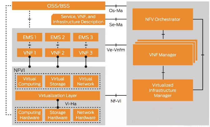
The standard architecture of NFV includes three parts: NFVI, MANO and VNFs. The goal of Network Function Virtualization (NFV) technology is to provide network functions on standard servers, rather than on custom devices.

NFVI is also called NFV Infrastructure, a general virtualization layer that includes the virtualization layer (hypervisor or container management system, such as Docker, and vSwitch) and physical resources. NFVI provides the VNF operating environment, including the required hardware such as computing, network, storage resources, etc. and software including hypervisor, network controller, storage manager and other tools.

VNF: Traditional hardware-based network elements can be called PNF. VNF and PNF can be networked separately or in combination to form a so-called service chain to provide E2E network services required in specific scenarios.

The overall management and orchestration of NFV is realized through MANO (Management and Orchestration), which is composed of NFVO (NFV Orchestrator), VNFM (VNF Manager) and VIM (Virtualised infrastructure manager).

VIM: It usually runs in the corresponding infrastructure site. It is an NFVI management module that mainly implements resource discovery, virtual resource management and allocation, and fault handling, and provides resource support for VNF operation.

VNFM: Mainly manage the life cycle of VNF, such as online and offline, status monitoring, image onboard.

NFVO: NS (NetworkService) life cycle management module, responsible for coordinating the control and management of NS, the VNFs that make up the NS, and the virtual resources that carry each VNF.

OSS/BSS: The management function of the service provider is not a functional component within the NFV framework, but NFVO needs to provide an interface to OSS/BSS.

The above is the news sharing from the PASSHOT. I hope it can be inspired you. If you think today’ s content is not too bad, you are welcome to share it with other friends. There are more latest Linux dumps, CCNA 200-301 dumpsCCNP Written dumps and CCIE Written dumps waiting for you.
Learn DLSW routing technology in three minutes

Today we have a comprehensive understanding of DLSW technology.

DLSw (Data Link Switching) is developed by APPN (Advanced Peer-to-Peer Networking) and Implementers Workshop (AIW) to implement a method of carrying SNA (System Network Architecture) through TCP/IP. 

SNA is a network architecture corresponding to the OSI reference model launched by IBM in the 1970s. To realize the SNA protocol across the WAN transmission, one of the solutions is DLSw technology.

Using DLSw technology, it is also possible to realize SDLC (Synchronous Data Link Control) link protocol across TCP/IP transmission. First convert the SDLC format message to LLC2 format message, and then interconnect with the remote end through DLSw. In this way, DLSw also supports the interconnection of different media between LAN and SDLC.

DLSw currently has two versions: DLSw1.0 and DLSw2.0.

The DLSw implemented based on RFC 1795 is version DLSw1.0; in order to improve product maintainability and reduce network overhead, the system implements DLSw2.0 version based on RFC 2166.

In DLSw2.0, the function of supporting sending UDP inquiry messages in multicast and unicast mode is added. When the communication peer is also DLSw2.0, the two can use UDP packets to inquire about reachability information, and only establish a TCP connection when there is a data transmission demand.

There were many problems in version 1.0, so DLSW2.0 version came later:

Let’s see what are the problems:

1. The problem of TCP connection: All messages (including inquiry messages, circuit establishment request messages, and data messages) are transmitted using TCP connections. First establish two TCP connections. After the performance exchange is completed, disconnect one TCP connection. This caused a waste of network resources to a certain extent.

2. Flooding of broadcast messages: When there is no reachable path information in the reachable information list of DLSw or there is too little reachable path information, the inquiry messages will flood the WAN through the established TCP connections.

3. Poor maintainability: When the link is interrupted, DLSw1.0 uses two types of messages to notify the opposite end, but it cannot tell the opposite end what caused the link interruption. It is difficult to determine the problem.

DLSw2.0 improvements:

1. Use UDP packets to query peer addresses: In order to avoid establishing unnecessary TCP connections, DLSw2.0 generally does not use TCP connections to send inquiry packets, but uses UDP packets instead.

2. Establish a single TCP channel: When there is a need to establish a link, a TCP connection is established between the source DLSw2.0 router and the target DLSw2.0 router.

3. Enhanced maintainability: Five reasons for circuit interruption are defined: unknown error detected, DISC frame received by DLSw from the terminal, DLC error detected by the terminal, circuit standard protocol error and system initialization.

DLSW+: Data linkswitching Plus — DLSw+ is a method of transmitting SNA and NetBIOS data in a wide area network or campus network. The terminal system can be connected via Token Ring, Ethernet, synchronous SDLC protocol or FDDI Go online.

DLSw+ can convert data between different media, terminate the data link locally, keep the response, keepalive and close the polling information of the WAN. The data link layer terminates locally and also eliminates control timeouts caused by network congestion or re-routing. Finally, DLSw+ also provides a dynamic search for SNA or NetBIOS resource mechanism and high-number algorithms to minimize broadcast transmission.

In the document, DLSw+ routers can be regarded as peerrouters, peers and partners. The connection between two DLSw+ routers is called a peer connection. A DLSw circuit includes the data link control connection between the initial terminal system and the initial router, the connection between the two routers (usually a TCP connection), and the data link control connection between the destination terminal system and the destination router. A single peer connection can support multiple circuits.

DLSW+ comparison DLSW standard adds four new points:

①Scalability-a method to build IBM network to reduce the amount of broadcast transmission and enhance network scalability.

② Practicality-quickly and dynamically find related paths and optionally use multiple active peers and ports for load balancing.

③Transmission flexibility-high-performance transmission avoids network interruption caused by timeout.

④Operation mode-dynamically detect the performance of peer routers and detect them according to their performance.

DLSW+ link establishment:

The establishment of a link for a group of end systems includes searching for target resources and setting up the data link connection of the end system. In the local area network, the SNA device sends a detection frame with the destination MAC address to look for other SNA devices. When a DLSw router receives the detection frame, it sends a canureach frame to every partner router it can reach. If one of the DLSw partners can reach the specified MAC address, it responds with an icanreach frame.

Each router and the local SNA designate the data link connection between the system and the TCP connection between DLSwpartner. This link is uniquely identified by the source and destination link numbers. Each link number is in turn composed of source and destination MAC addresses, source and destination chains Road service access point and a data link control number to define. Once the link is established, the information frame can be transmitted.

The above is the news sharing from the PASSHOT. I hope it can be inspired you. If you think today’ s content is not too bad, you are welcome to share it with other friends. There are more latest Linux dumps, CCNA 200-301 dumpsCCNP Written dumps and CCIE Written dumps waiting for you.
The association and difference between Cisco IGRP and EIGRP

Today we will learn the routing protocols IGRP and EIGRP.

IGRP:

An interior gateway routing protocol designed by Cisco in the mid-1980s. Use combined user configuration metrics, including latency, bandwidth, reliability, and load. It has a high span within the same autonomous system and is suitable for complex networks. Cisco IOS allows router administrators to weight the IGRP network bandwidth, delay, reliability, and load to affect the calculation of the metric.

It is a Cisco proprietary routing protocol that provides routing functions in an autonomous system (AS: autonomous system). In the mid-1980s, the most commonly used internal routing protocol was RIP. Although RIP is very useful for realizing the routing selection of small or medium-sized interconnection networks of the same type, with the continuous development of the network, its limitations have become more obvious. The practicality of Cisco routers and the powerful functionality of IGRP have led many small Internet organizations to use IGRP instead of RIP. As early as the 1990s, Cisco introduced enhanced IGRP to further improve the operational efficiency of IGRP.

For greater flexibility, IGRP supports multi-path routing services. In Round Robin mode, two lines of the same bandwidth can run a single communication stream. If one of the lines fails to transmit, the system will automatically switch to the other line. Multipath can be multipath lines with different standards but still work.

IGRP maintains a set of timers and variables containing time intervals. Including update timer, expire timer, hold timer and clear timer. The update timer specifies how often the route update message should be sent. This value in IGRP defaults to 90 seconds. The invalidation timer specifies how long the router should wait before declaring that the route is invalid when there is no routing update message for a specific route. This value in IGRP defaults to three times the update period. The hold time variable specifies the hold-down period. This value in IGRP defaults to three times the update period plus 10 seconds, which is 280 seconds. Finally, the empty timer specifies the time the router waits before emptying the routing table. The default value of IGRP is seven times the route update cycle.

EIGRP:

EIGRP: EnhancedInterior Gateway Routing Protocol is the enhanced interior gateway routing protocol. It is also translated as an enhanced internal gateway routing protocol. EIGRP is a private agreement of Cisco (it has been publicized in 2013). EIGRP combines the link state and distance vector routing protocol of the Cisco proprietary protocol, and adopts DUAL to achieve rapid convergence, and can not send periodic routing update information to reduce bandwidth occupation.

EIGRP uses DUAL to achieve rapid convergence. Routers running EIGRP store neighbors’ routing tables, so they can quickly adapt to changes in the network. If there is no suitable route in the local routing table and there is no suitable backup route in the topology table, EIGRP will query neighbors to find alternative routes. The query will continue to propagate until an alternative route is found or it is determined that there is no alternative route. Moreover, EIGRP sends partial updates instead of periodic updates, and only sends when the routing path or metric changes. Only the information of the changed link is included in the update, instead of the entire routing table, which can reduce bandwidth usage. In addition, it also automatically limits the propagation of these partial updates and only delivers them to the routers that need them. Therefore, EIGRP consumes much less bandwidth than IGRP. This behavior is also different from link state routing protocols, which send updates to all routers in the area.

EIGRP uses a variety of parameters to calculate the metric value to the target network, including Bandwidth, delay, reliability, loading, and MTU. These 5 parameters are represented by K values, namely K1, K2, K3, K4, K5, so if two The five K values between two EIGRP routers are different, which means that the two parties have different methods of calculating the metric value; whether it is EIGRP or other protocols, when the bandwidth needs to be used to calculate the metric, only the bandwidth in the outbound direction of the interface is calculated, and the inbound direction of the interface is calculated. It is not counted, that is, on a link, the bandwidth of only one outgoing interface will be calculated, and the bandwidth of the incoming interface will be ignored.

The 5 standards of EIGRP Metric:

bandwidth:

10 divided by the 7th power of the lowest bandwidth between the source and target multiplied by 256 (10 divided by the 7th power of 10 by the minimum bandwidth in Kbit/s, then added to the sum of delays divided by 10, and finally multiplied by 256 ).

Delay: The cumulative delay of the interface is multiplied by 256, and the unit is 10 microseconds.

Reliability: The most unreliable reliability value between the source and the destination based on keepalive.

Load: The value of the worst load between the source and the destination based on the packet rate and interface configuration bandwidth.

Maximum transmission unit: The smallest MTU in the path. MTU is included in the routing update of EIGRP, but generally does not participate in the calculation of EIGRP degrees.

The above is the news sharing from the PASSHOT. I hope it can be inspired you. If you think today’ s content is not too bad, you are welcome to share it with other friends. There are more latest Linux dumps, CCNA 200-301 dumpsCCNP Written dumps and CCIE Written dumps waiting for you.

Detailed explanation of MLDsnooping technology for IPv6 multicast

MLDsnooping is the abbreviation for Multicast Listener Discovery Snooping. It is an IPv6 multicast restriction mechanism running on Layer 2 devices, used to manage and control IPv6 multicast groups.

The Layer 2 device running MLD Snooping analyzes the received MLD messages, establishes a mapping relationship between ports and MAC multicast addresses, and forwards IPv6 multicast data based on this mapping relationship. When the Layer 2 device is not running MLD Snooping, IPv6 multicast data packets are broadcast at Layer 2. When the Layer 2 device is running MLD Snooping, it is known that multicast data packets of IPv6 multicast groups will not be broadcast at Layer 2. Broadcast, and be multicast to designated receivers at Layer 2. 

MLDsnooping uses Layer 2 multicast to forward information only to receivers in need, which can bring the following benefits:

1. Reduce the broadcast message in the second layer network and save the network bandwidth;

2. Enhance the security of IPv6 multicast information;

3. It is convenient to realize the separate billing for each host.

The specific processing methods for different MLD actions by switches running MLD Snooping are as follows:

1. General group query

The MLD querier periodically sends MLD general query messages to all hosts and routers (FF02::1) in the local network segment to query which IPv6 multicast group members are on the network segment. When receiving an MLD general query message, the switch forwards it through all ports in the VLAN except the receiving port, and performs the following processing on the receiving port of the message:

If the dynamic router port is already included in the router port list, reset its aging timer. If the dynamic router port is not yet included in the router port list, add it to the router port list and start its aging timer.

2. Report membership

When an IPv6 multicast group member host receives an MLD query message, it will reply with an MLD membership report message. If a host wants to join an IPv6 multicast group, it will actively send an MLD membership report message to the MLD querier to declare to join the IPv6 multicast group. When receiving an MLD membership report message, the switch forwards it through all router ports in the VLAN, parses the IPv6 multicast group address that the host wants to join from the message, and performs a command on the receiving port of the message. Treat as follows:

If there is no forwarding entry corresponding to the IPv6 multicast group, create a forwarding entry, add the port as a dynamic member port to the outgoing port list, and start its aging timer;

If the forwarding entry corresponding to the IPv6 multicast group already exists, but the port is not included in the outgoing port list, the port is added to the outgoing port list as a dynamic member port, and its aging timer is started;

If the forwarding entry corresponding to the IPv6 multicast group already exists and the dynamic member port is already included in the outgoing port list, the aging timer is reset.

3. Leave the multicast group

When a host leaves an IPv6 multicast group, it will send an MLD leave group message to notify the multicast router that it has left an IPv6 multicast group. When the switch receives an MLD leave group message from a dynamic member port, it first determines whether the forwarding table entry corresponding to the IPv6 multicast group to leave exists, and the outgoing port list of the forwarding table entry corresponding to the IPv6 multicast group Whether the receiving port is included in.

4. MLD SnoopingProxying

By configuring the MLD Snooping Proxying (MLD Snooping proxy) function on the edge device, the number of MLD report and leave messages received by the upstream device can be reduced, and the overall performance of the upstream device can be effectively improved. A device configured with MLD Snooping Proxying function (called MLD Snooping proxy device) is equivalent to a host in the view of its upstream device, and equivalent to a querier from its downstream host.

Although the MLD Snooping proxy device is equivalent to a host from its upstream device, the MLD membership report suppression mechanism on the host will not take effect on the MLD Snooping proxy device.

How the MLD snooping agent device processes MLD messages:

1. General group query message: After receiving the general group query message, it is forwarded to all ports in the VLAN except the receiving port; at the same time, a report message is generated according to the locally maintained group membership and sent to all router ports.

2. MLD last listener query message/MLD specific source group query message: If there are member ports in the forwarding entry corresponding to the group, the report message of the group will be returned to all router ports.

3. MLD report message:

1) If there is no forwarding entry corresponding to the group, create a forwarding entry, add the receiving interface as a dynamic member port to the outgoing interface list, start its aging timer, and then send the report of the group to all router ports Message

2) If the forwarding entry corresponding to the group already exists and the dynamic member port is included in the outgoing interface list, reset its aging timer;

3) If the forwarding entry corresponding to the group already exists, but the receiving interface is not included in the outgoing interface list, the interface is added to the outgoing interface list as a dynamic member port, and its aging timer is started.

4. MLD leave message: Send a group-specific query message for the group to the receiving interface. Only when the last member port in the forwarding entry corresponding to a multicast group is deleted, the leave message of the group will be sent to all router ports.

The above is the news sharing from the PASSHOT. I hope it can be inspired you. If you think today’ s content is not too bad, you are welcome to share it with other friends. There are more latest Linux dumps, CCNA 200-301 dumpsCCNP Written dumps and CCIE Written dumps waiting for you.

The difference between MPLS and IP

MPLS VS IP
Principle of IP forwarding:

The router checks the destination IP address of the data packet and forwards the data according to the routing table. IP network, forward data according to the IP header.

Principle of MPLS forwarding:

The MPLS router (LER LSR) receives the MPLS data message and forwards the MPLS data message according to label forwarding. MPLS multi-protocol label switching [Multi-Protocol Label Switching] can carry multiple routing protocols.

The most basic IP header:

MPLS header structure, usually MPLS header has 32 bits, including:

· 20bit used as a label (Label)

· 3-bit EXP, not specified in the protocol, usually used as COS

· 1 bit of S, used to indicate whether it is the bottom of the stack, the surface MPLS labels can be nested.

· 8 bit TTL

MPLS terminology

Label: It is equivalent to the IP address in the IP network, and the local route is meaningful.

FEC: It is equivalent to the network prefix in the IP network, and one routing entry corresponds to one FEC. Each FEC generates a corresponding label. Example: 192.168.1.0/24 network prefix, 192.168.1.1~192.168.1.254 belong to the same FEC.

LSP: Label switching channel, the path of data flow is LSP.

LSR: Label switching router, a router in the MPLS network

LER: Label switching edge router, which belongs to the MPLS network edge router.

How MPLS forwarding works

1. How to generate label forwarding entries?

Note: The label forwarding table is similar to the routing table in the IPv4 network.

The router generates a corresponding label for each routing entry, and puts the label into the label forwarding table.

There needs to be a mapping relationship (FEC) between the router and the label

2. How to insert MPLS label header into IP message on LER?

When the data packet enters the MPLS domain from the IP domain, the LER inserts an MPLS header, and the specific label paper is generated according to the label forwarding table.

3. How does the router in the MPLS domain deliver packets to the destination?

The LSR device exchanges the label of the MPLS packet header according to the label forwarding table.

For LER equipment, when an IP message enters, it searches the label forwarding table, and applies a label operation (PUSH) to the IP message. When the IP message leaves, it performs a pop-up operation (POP) on the label message and forwards it according to the IP route.

Principle of IP network forwarding:

In the hop-by-hop IP transmission, the longest matching search (possibly multiple times) in the routing table must be performed at each hop passed, and the speed is slow.

Principle of MPLS forwarding:

In MPLS label forwarding, a label forwarding channel (LSP) is established for messages through pre-allocated labels. At each device that the channel passes through, only fast label switching is required (one search)

IP forwarding VS MPLS forwarding

MPLS forwarding advantages:

① There are very few header fields, and routers process this header efficiently.

②The forwarding process is simple, check the label

③MPLA forwarding, but it is necessary to view the label forwarding table

MPLS forwarding defects:

①The survival of the label depends on the IGP protocol and the routing table

The above is the news sharing from the PASSHOT. I hope it can be inspired you. If you think today’ s content is not too bad, you are welcome to share it with other friends. There are more latest Linux dumps, CCNA 200-301 dumpsCCNP Written dumps and CCIE Written dumps waiting for you.

Cisco certification CCIE LAB test room reopened

Important news! The Cisco certification CCIE LAB test room is reopened! The IE preparation guide teaches you to quickly win the new upgraded IE in all directions

Since the domestic epidemic broke out last year and the global epidemic is still continuing today, for network engineers, the biggest impact is no more than the suspension of the CCIE exam plan.

However, the situation of the epidemic situation getting better also made us receive such good news in August. On August 3rd, Cisco’s official website issued a notice about the reopening of some CCIE LAB examination rooms at home and abroad. This is for students who have been waiting for exam preparation. It’s great news!

Then follow the editor to see the latest examination room developments about the CCIE exam in the official notice issued by Cisco

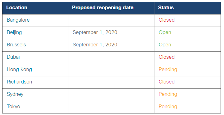
1. The examination rooms currently planned to be reopened, to be opened, and still closed are:

Cisco CCIE LAB latest examination room development

Beijing Examination Center & Brussels Examination Center

Unless there are special circumstances, it will reopen on September 1st

Opening hours of Hong Kong, Sydney and Japan test rooms are to be determined

Bangalore, Dubai, and Richardson test rooms remain closed

2. Exam seat details: After logging in to my Cisco account, check the exam seat details. After the reservation is successful, you will receive an exam information confirmation email.

3. Regarding the examination room environment and matters needing attention: 

①Will the examination room that is planned to open be closed again without prompt notification?

This is possible, but we hope that this situation will not happen unless the test site suddenly deteriorates due to the epidemic in a city, test location, etc. If the reopened test room is closed again due to the epidemic, there is a chance to reapply for the test .

In the event that the exam room is closed, students who have booked the exam will be notified by the Cisco service team according to the contact information you left in the registration information.

②What should I pay attention to during the exam?

*People who test positive for COVID-19, show symptoms of infection, or have close contacts are strictly prohibited from entering the examination room

*Specific test sites may have specific restrictions, subject to on-site arrangements

*After the reservation is successful, you will enter the examination room visitor management system and receive a welcome email. You need to fill in the relevant information and complete the registration.

First of all, wearing a mask all the way is the most basic. It is recommended to bring your own disposable disinfectant or hand sanitizer. The hygiene of the examination room will be disinfected and cleaned every day, especially for door handles and elevators and other devices that need to be touched to increase the frequency of disinfection.

The number of open exam places is limited to no more than 50%. For example, if there are 6 seats in an exam room, only 2 candidates will take the exam. LAB exams in different directions may not be all open on the same day.

Due to the epidemic, the cafeteria where the examination room provides meals is not open, and some examination rooms may not be able to deliver food, so it is best to bring your own food and water just in case.

③What should I do if the temporary plan has changed and I cannot take the test on the test date?

The payment policy of 90 days in advance for the previous LAB exam has been suspended, and the payment can be completed 2 days before the exam.

④Is there any restrictions on entry and exit from other cities or countries to the country/region where the examination room is reopened?

According to the travel and entry policy requirements of the city/national government where the test site is located, please check whether travel is restricted in advance, and then it is more secure to make a point.

I believe that seeing this, everyone’s learning heart has been rekindled! Joining PASSHOT CLUB, with the gradual opening of the Cisco CCIE LAB examination room, PASSHOT teachers will do their best to complete the preparation of the exam content as soon as possible.

The above is the news sharing from the PASSHOT. I hope it can be inspired you. If you think today’ s content is not too bad, you are welcome to share it with other friends. There are more latest Linux dumps, CCNA 200-301 dumpsCCNP Written dumps and CCIE Written dumps waiting for you.

Basic principles of NAT64

Today we will understand the overview of the NAT64 protocol.

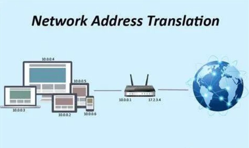
NAT (Network Address Translation, network address translation) was proposed in 1994. When some hosts in the private network have been assigned local IP addresses, but now they want to communicate with hosts on the Internet, the NAT method can be used. Defined in RFC 1631. The original purpose of NAT is similar to CIDR, and it is also to slow the exhaustion of the available IP address space. The implementation method is to use a small number of public IP addresses to represent a large number of private IP addresses. Over time, people have found that NAT is very useful for applications such as network migration, network convergence, and server load sharing.

IPv4 was first created in the 1970s, earlier than the current Internet, earlier than the World Wide Web, earlier than the ubiquitous broadband service that is always online, and earlier than smart phones. At the beginning of its creation, the 4.3 billion addresses owned by IPv4 are extremely rich for the trivial experimental TCP/IP network to be supported, but the number of people connected to the Internet has exceeded 3.2 billion, and there are a large number of other devices connected to the Internet. .

No matter what scale the IoT will develop in the future, the current 4.3 billion addresses are far from meeting the demand. From a capacity perspective, we ran out of IPv4 addresses in the mid-1990s. We just use extended IPv4 available addresses for the Internet of Things that far exceeds the capacity of IPv4 addresses through many means.

So IPv6 is not necessary, but there are still many difficulties before transitioning to IPv6 networks.

1. The Internet lacks centralized management and is an alliance of a large number of independently managed autonomous systems, so there is no way to force or coordinate everyone to switch from IPv4 to IPv6.

2. The network fully supports IPv6 requires a lot of financial resources, manpower and technology.

3. IPv6 and IPv4 are not backward compatible. IPv6 was first born in the 1990s. At that time, designers believed that operators would definitely actively deploy IPv6. Few people thought that IPv6 deployment would face many obstacles.

NAT64 is a stateful network address and protocol translation technology. Generally, it only supports access to IPv4 network resources through the user-initiated connection on the IPv6 network side. However, NAT64 also supports manual configuration of static mapping relationships, so that IPv4 networks can actively initiate connections to access IPv6 networks.

Although most devices now support IPv6, there are still many older devices that only support IPv4. These devices need to be interconnected through an IPv6 network in some way. NAT64 can realize IPv6 and IPv4 network address and protocol conversion under TCP, UDP, ICMP protocol.

And because IPv6 is not compatible with IPv4, there must be necessary migration mechanisms, such as dual stack, tunneling, and conversion.

1. Dual-stack interface: The simplest way to maintain the coexistence of IPv4 and IPv6 is to configure two protocols for the interface. Which version of the IP protocol is used depends on the version of the data packet received from the device or the type of address returned by DNS when querying the device address. Although dual stack is an expected migration method from IPv4 to IPv6, the premise is that the migration process must be completed before IPv4 addresses are exhausted.

2. Tunnel: The tunnel also solves the problem of coexistence. The tunnel allows devices or sites of one protocol version to traverse the network segment of another protocol version (including the Internet), so that two IPv4 devices or sites can exchange IPv4 packets through the IPv6 network, and between two IPv6 devices or sites It is also possible to exchange IPv6 data packets through an IPv4 network.

3. Conversion: The conversion technology changes the packet header of one protocol version to the packet header of another protocol version, thus solving the interoperability problem between IPv4 devices and IPv6 devices.

A simple NAT64 setting may be that two interfaces of a device are respectively connected to the gateway of the IPv4 network and the IPv6 network. The traffic of the IPv6 network is routed through the gateway, which performs all the necessary translation of the packets transmitted between the two networks. However, this translation is not symmetric, because the IPv6 address space is much larger than the IPv4 address space, so it is impossible to perform one-to-one address mapping. 

Generally speaking, NAT64 is designed to be used when IPv6 hosts initiate communication. But there are also some mechanisms that allow reverse scenarios, such as static address mapping.

Not every type of resource can be accessed with NAT64. Protocols with embedded IPv4 literal addresses (such as SIP and SDP, FTP, WebSocket, Skype, MSN, etc.) cannot be supported. For SIP and FTP, the application layer gateway (ALG) technology can solve the problem. Up to now, NAT64 is not a good solution. The current limitations of NAT64 are as follows:

1. Without static address mapping entries, IPv4 devices are not allowed to initiate session requests to IPv6 devices;

2. The software has limited support for NAT64;

3. Like all other converters, IP multicast is not supported;

4. Many applications do not support it.

The above is the news sharing from the PASSHOT. I hope it can be inspired you. If you think today’ s content is not too bad, you are welcome to share it with other friends. There are more latest Linux dumps, CCNA 200-301 dumpsCCNP Written dumps and CCIE Written dumps waiting for you.